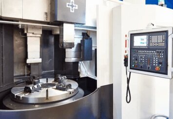
Comparison of 5 Efficient Chip Removal Solutions for CNC Vertical Lathe Machines
Struggling with Poor Chip Removal During Deep Hole Machining on CNC Vertical Lathe Machines?
Deep hole machining typically has a large length-to-diameter ratio and a confined processing environment. When chip removal is inefficient, chips accumulate within the hole, which not only scratches the machined surface, worsening the surface roughness from Ra0.8μm to over Ra3.2μm but also causes a sharp rise in cutting temperature, increasing tool wear by 5 to 8 times. In severe cases, it can even lead to tool breakage, causing machining interruptions. Currently, five main solutions have been developed to achieve efficient chip removal during deep hole machining on CNC vertical lathe machines: vibration-assisted chip removal, compressed air-assisted chip removal, and others.
This article will compare and analyze the five most common chip removal technologies, providing a scientific reference for process optimization.

I. Causes of Poor Chip Removal
In deep hole machining on CNC vertical lathe machines, the main reasons for poor chip removal include:
· Large Chip Volume: During deep hole machining, chips are typically long and hard, making it difficult for them to be quickly removed from the cutting area.
· Insufficient Coolant Pressure: If the coolant flow is inadequate or the spray angle is incorrect, chips cannot be effectively flushed out, leading to accumulation.
· Tool and Workpiece Design Issues: In certain deep hole machining processes, tool design and other factors may negatively affect chip removal efficiency.
II. Comparison of 5 Efficient Chip Removal Solutions
1.High-Pressure Coolant System (HPC)
Principle: High-pressure pumps (30-200 Bar) direct coolant to the cutting area, forcing chips to be removed.
Advantages:
· Increases chip removal efficiency by over 60% for materials like cast iron and stainless steel.
· Simultaneously reduces cutting temperature (measured reduction of 150-250°C). Limitations:
· Requires a dedicated high-pressure pump station, with an initial investment of over $25k.
· Risk of coolant atomization pollution (requires a recovery system).
Applicable Scenarios: Heavy-duty cutting, large-diameter deep hole machining.
2. Through-Tool Coolant Technology
Principle: Coolant flows through the tool holder and exits through precision-designed microholes (typically 0.2-0.5mm in diameter) directly onto the cutting area.
Technological Breakthroughs:
· Sandvik JetCut Pro tools achieve 0.1mm precision in microhole-directed coolant spray.
· Chip breakage is controlled to a length of under 3mm (per ISO 3685 standard). Limitations:
· Requires advanced CAD/CAM technology for design and specialized manufacturing methods like EDM and laser machining, increasing tool manufacturing costs by 30%-50%.
· Difficult to implement internal cooling designs on special or complex-shaped tools, such as non-standard spiral cutters.
· Regular cleaning of internal cooling channels is necessary.
3. Vibration-Assisted Chip Breaking
Principle: Axial vibrations (10-200Hz) are applied to the spindle (vibration amplitude of 0.01-0.1mm), dynamically breaking chips and reducing entanglement probabilities. Limitations:
· Requires modification of the machine control system and skilled operators.
4. Compressed Air-Assisted Chip Removal
Principle: Compressed air (0.6-0.8MPa) combined with minimal lubrication (MQL) is used, with air nozzles positioned at a 15°-30° angle to the cutting point. Environmental Benefits:
· Reduces coolant usage by 90% compared to traditional flood cooling.
· Suitable for industries with high cleanliness requirements, such as medical and food machinery. Considerations:
· Requires explosion-proof design for machining light metals like aluminum and magnesium.
5. Chip Removal Groove Optimization
Design Features:
· Spiral Angle Optimization: 35°-45° double spiral groove design improves chip flow.
· Nano Coating: TiAlN coating reduces friction by over 20%.
· Variable Lead Structure: Dynamically adjusts groove shape based on different materials. Typical Case: Kennametal TX series grooving tools achieve continuous chip removal of over 15m in titanium alloy machining.
III. Technology Selection Comparison Table
| Indicator | High-Pressure Coolant | Through-Tool Coolant | Vibration-Assisted Chip Breaking | Compressed Air Assisted Chip Removal | Chip Removal Groove Optimization |
| Initial Cost | ★★★☆☆ | ★★☆☆☆ | ★★★★☆ | ★☆☆☆☆ | ★★☆☆☆ |
| Chip Removal Efficiency | ★★★★★ | ★★★★☆ | ★★★☆☆ | ★★☆☆☆ | ★★★☆☆ |
| Process Compatibility | ★★★☆☆ | ★★★★☆ | ★★☆☆☆ | ★★★★★ | ★★★★★ |
| Maintenance Complexity | ★★☆☆☆ | ★★★☆☆ | ★★★★☆ | ★☆☆☆☆ | ★☆☆☆☆ |
IV. Selection Recommendations
· Batch Production: High-pressure coolant combined with through-tool coolant is recommended.
· Small Batch, Multiple Varieties: The combination of groove optimization and compressed air is suggested.
· Ultra-High Precision Requirements: Vibration-assisted chip removal should be paired with a dynamic compensation system.
While five effective chip removal solutions have been presented in this article, the choice of solution cannot be generalized. Key factors such as machining materials, workpiece precision, production scale, and cost budget must be considered in the decision-making process. If you still have questions regarding chip removal during deep hole machining on vertical machining centers or are looking for the right vertical machining center for your needs, feel free to visit Minno for free consultations!

 Email
Email sales1:+1 213 865 6527


